Unit 6 Overview: Geometric and Physical Optics
Related

N
NUM8ERS
0
0
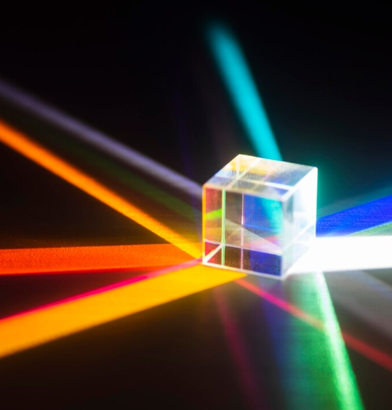
6.6 Interference and Diffraction
December 10, 2024
Save
N
NUM8ERS
0
0
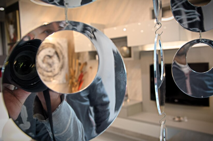
6.5 Images from Lenses and Mirrors
December 10, 2024
Save

N
NUM8ERS
0
0
6.4 Refraction, Reflection, and Absorption
December 10, 2024
Save

More By Author

N
NUM8ERS
0
0
Williams Syndrome - Everything you need to know
March 11, 2025
Save
N
NUM8ERS
0
0
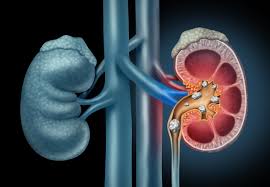
Kidney Stones Causes - Everything you need to know
March 11, 2025
Save

N
NUM8ERS
0
0
Progressive Supranuclear Palsy (PSP) - Everything you need to know
March 11, 2025
Save

N
NUM8ERS
0
0
Pheochromocytoma - Everything you need to know
March 11, 2025
Save