Images from Lenses and Mirrors: A Complete Guide
Light and optics are essential components of physics, and understanding how images are formed by lenses and mirrors is crucial for numerous scientific and practical applications. This guide dives into the principles of image formation, exploring both mathematical and conceptual frameworks.
Plane Mirrors
Plane mirrors, the simplest type of mirrors, have flat surfaces. When you look into a plane mirror, you see an image of yourself or an object nearby. But how is this image formed? Let’s break it down.
How Do Plane Mirrors Form Images?
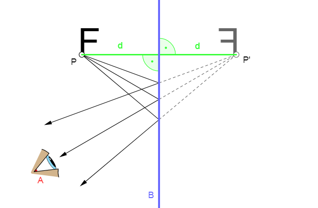
Light reflected from an object strikes the mirror and reflects back to our eyes. The direction of the reflected rays determines where we perceive the image.
Image Characteristics of Plane Mirrors
Location and Size:
- The image appears as far behind the mirror as the object is in front of it.
- The image has the same size as the object.
Real or Virtual:
- Virtual Image: The light rays don’t actually converge at the image location but appear to diverge from it.
Upright or Inverted:
- The image is upright and not flipped.
Key Points to Remember
- Plane mirrors always form virtual, upright, and same-size images.
- No light actually passes through the image location behind the mirror.
Spherical Mirrors: Concave and Convex
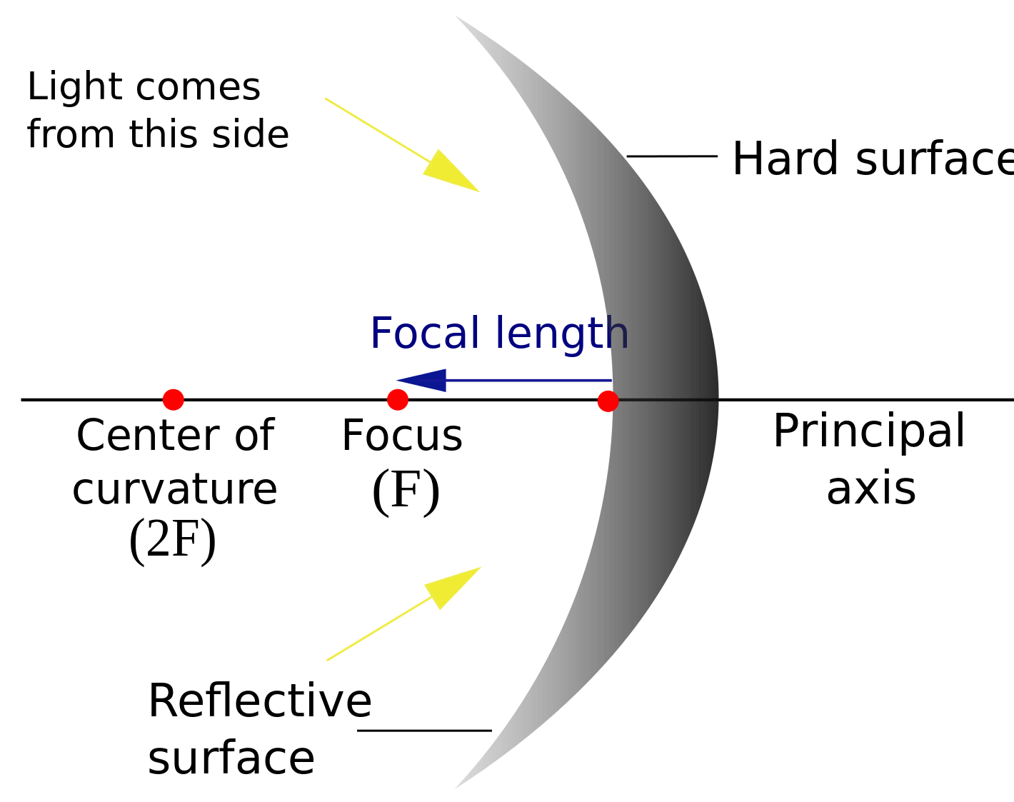
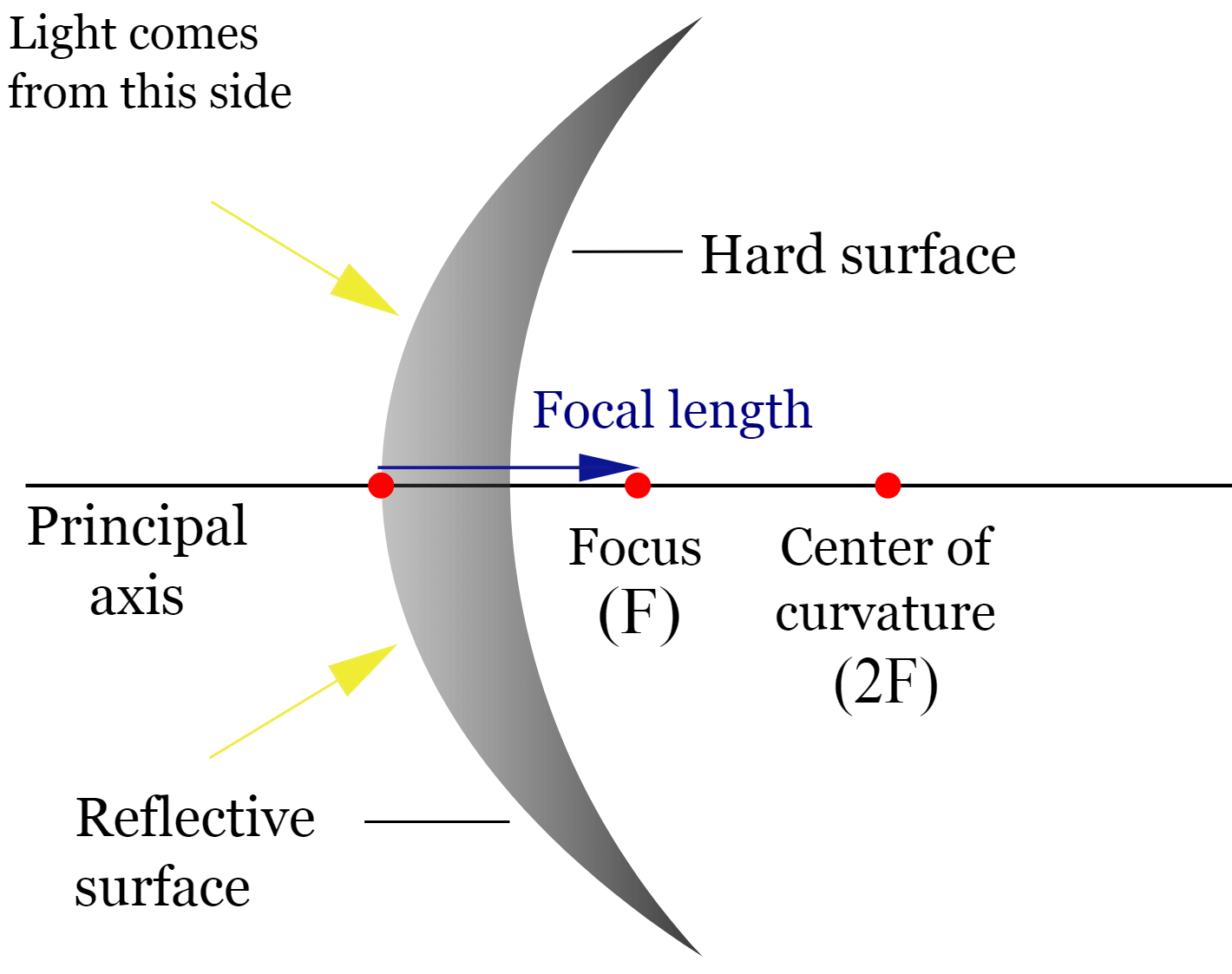
Spherical mirrors are curved mirrors that form part of a sphere’s surface. There are two types: concave mirrors (curved inward) and convex mirrors (curved outward).
Key Terminologies for Spherical Mirrors
- Principal Axis: The line passing through the mirror’s center and its curvature.
- Center of Curvature (C): The center of the sphere from which the mirror is derived.
- Radius of Curvature (R): The radius of the sphere.
- Focal Point (F): The point where light rays converge (for concave) or appear to diverge (for convex).
- Focal Length (f): The distance between the focal point and the mirror ().
Ray Tracing for Mirrors
Ray tracing is a graphical method to determine an image’s position and characteristics. Here are the rules:
Concave Mirrors:
- Rays parallel to the principal axis reflect through the focal point.
- Rays passing through the focal point reflect parallel to the principal axis.
- Rays passing through the vertex reflect symmetrically.
Convex Mirrors:
- Parallel rays reflect such that their extensions pass through the focal point.
- Rays directed toward the focal point reflect parallel to the principal axis.
- Rays passing through the vertex reflect symmetrically.
How to Determine the Image
- For real images: The image is on the same side of the mirror as the object.
- For virtual images: The image forms on the opposite side of the mirror.
The Mirror Equation
The mirror equation helps calculate the image’s location:
Where:
- : Focal length
- : Object distance
- : Image distance
The magnification equation determines the image’s size:
Where:
- : Image height
- : Object height
Lenses: Converging and Diverging
Lenses are optical devices that form images by refracting light. There are two main types:
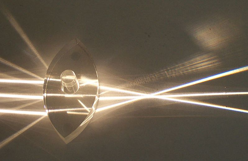
- Converging (Convex) Lens: Brings parallel rays of light to a single focal point on the far side of the lens.
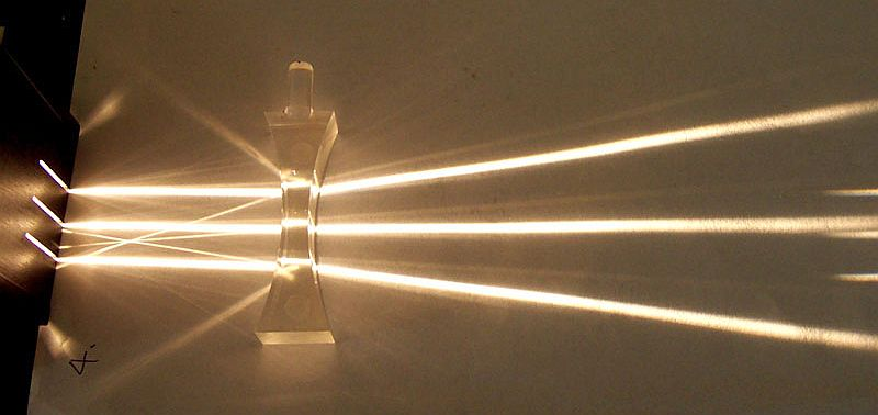
- Diverging (Concave) Lens: Causes parallel rays to spread out, appearing to diverge from a focal point on the same side as the incoming light.
Ray Tracing for Lenses
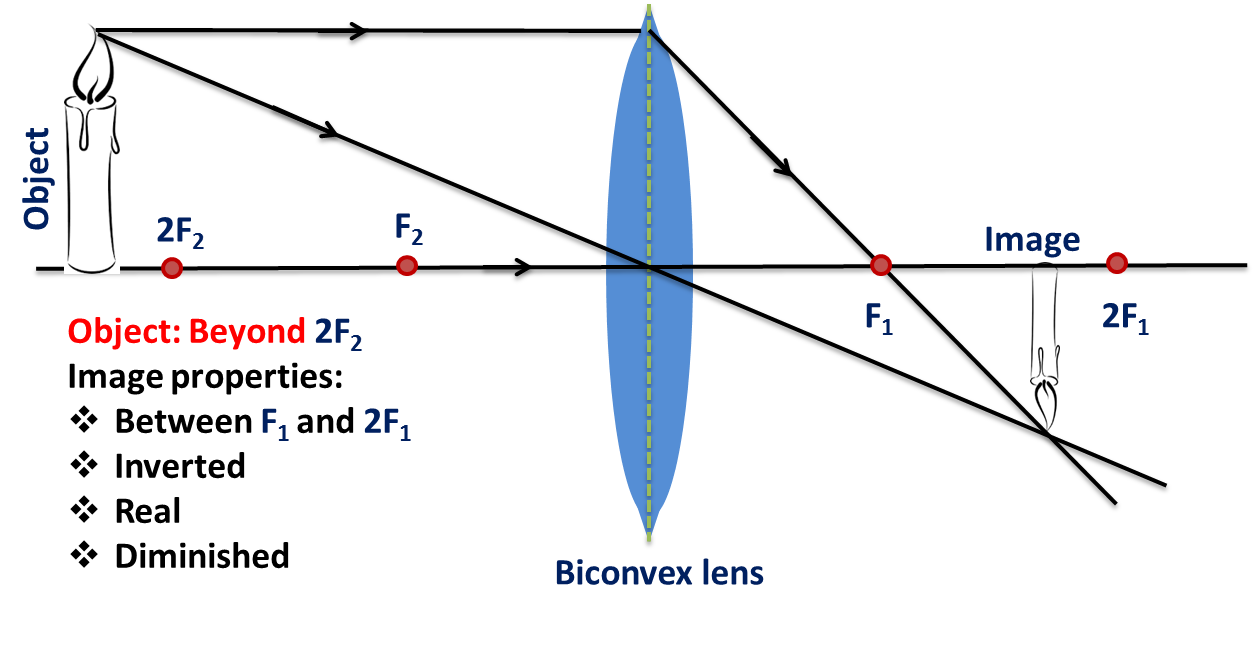
Ray tracing with lenses helps determine an image’s size, orientation, and location.
Convex Lenses:
- Rays parallel to the principal axis pass through the focal point.
- Rays passing through the focal point emerge parallel to the principal axis.
- Rays passing through the lens’s center are undeflected.
Concave Lenses:
- Parallel rays diverge such that their extensions pass through the focal point.
- Rays directed toward the focal point emerge parallel to the principal axis.
- Rays passing through the lens’s center are undeflected.
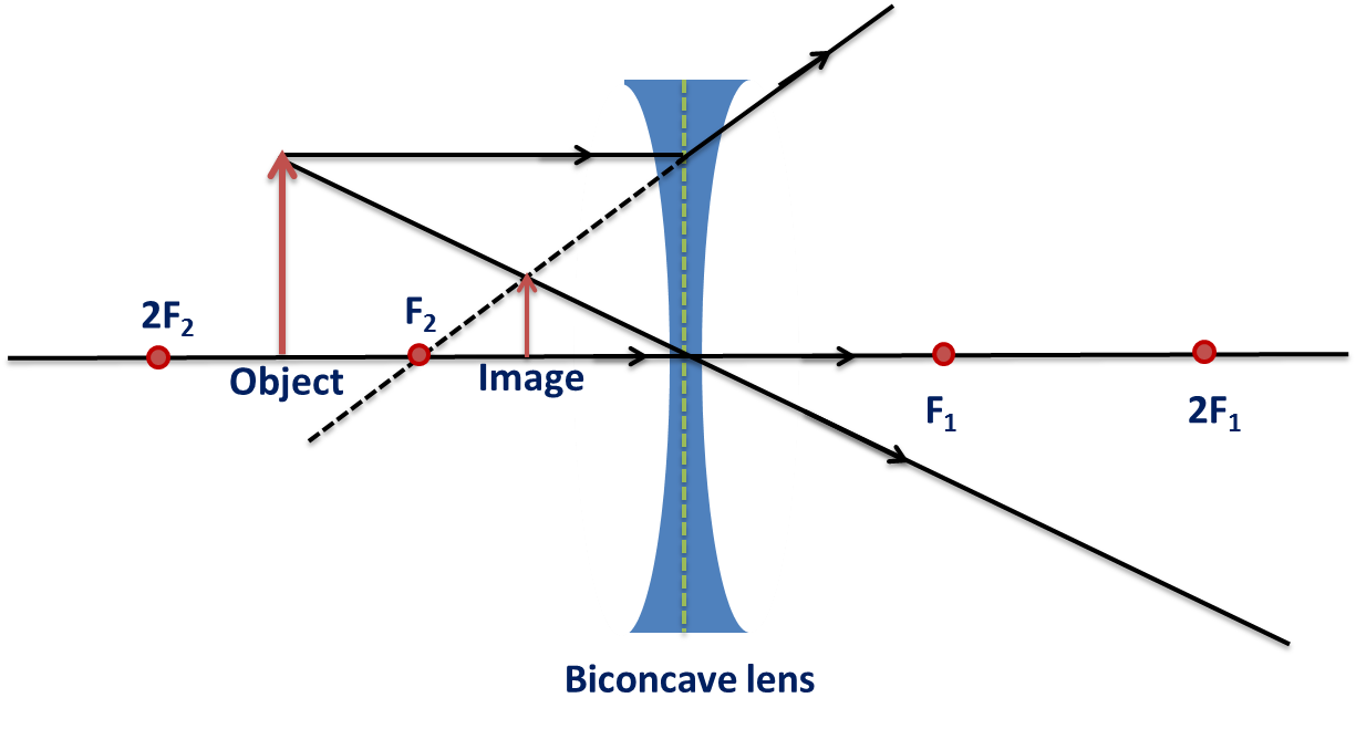
Lens Equation
The same equations for mirrors apply to lenses:
The focal length () is positive for converging lenses and negative for diverging lenses.
Applications of Lenses and Mirrors
- Optical Devices: Used in telescopes, microscopes, and cameras to focus light and form images.
- Eyeglasses and Contact Lenses: Correct vision by refocusing light onto the retina.
- Rearview Mirrors: Convex mirrors provide a wider field of view.
- Lasers and Fiber Optics: Utilize lenses and mirrors for precision in light transmission.
Practice Problems
A plane mirror produces an image that is:
E) Virtual, upright, and the same size as the object.An object is 20 cm from a converging lens with a focal length of 15 cm. The image is:
C) Real, inverted, and larger.A light beam passes through a concave lens. The image formed is:
B) Virtual, smaller than the object, and upright.An object 10 cm in front of a concave mirror with :
C) 10 cm (real image).
