Definition and Conservation of Electric Charge
Electric charge is a fundamental property of matter that causes it to experience a force in an electromagnetic field. This foundational concept is essential for understanding electric circuits, current flow, and resistance. In this blog, we will explore the conservation of electric charge, its relationship to current, and key tools and concepts used to measure and analyze circuits.
Conservation of Electric Charge
The principle of conservation of electric charge states that the total electric charge in a closed system remains constant over time. While charge can be transferred or distributed, it cannot be created or destroyed. This principle is critical for analyzing electric circuits and understanding the behavior of charge carriers.
Key Points:
Fundamental Law: Conservation of charge is a consequence of the law of conservation of mass-energy, ensuring that charge remains constant in a closed system.
Symmetry in Physics: This principle arises from the symmetry of physical laws under charge conjugation, where positive and negative charges are interchanged.
Applications: Understanding charge conservation helps predict current flow, the operation of batteries, and the behavior of electric fields and circuits.
In a circuit, the conservation of charge ensures that the flow of electric current remains continuous, and charge remains balanced across the system. Kirchhoff’s Junction Rule is derived from this principle and helps in analyzing complex circuits.
Electric Current ⚡️
Electric current is the rate at which charge flows through a circuit. It is defined by the formula: Where:
: Current (Amps, A)
: Charge passing through a point (Coulombs, C)
: Time (seconds, s)
Key Points:
Conventional Current: Defined as the flow of positive charge. Although electrons are the mobile charge carriers, this convention simplifies alignment with electric field directions and potential differences.
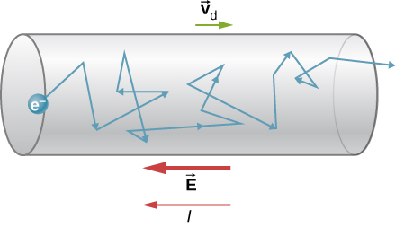
Microscopic Perspective: Current is related to the drift velocity of charge carriers, the average velocity of electrons moving through a conductor under an electric field.
Drift Velocity:
Drift velocity is influenced by the electric field strength, charge, and mass of the particle.
Higher conductivity materials exhibit higher drift velocities, making them better conductors of electricity.

Resistance and Conductivity
Resistance (Ω) measures how much a material opposes the flow of electric current. Resistivity (ρ) is the inherent property of a material determining its resistance.
Formula:
Where:
: Resistance
: Resistivity
: Length of the material
: Cross-sectional area
Higher resistance materials restrict current flow, while conductive materials like copper or silver allow charges to move more freely.
Circuit Measuring Tools 🛠️
To analyze circuits effectively, we use tools like ammeters and voltmeters:
Ammeters:
Measure electric current.
Connected in series with the circuit.
Have low internal resistance to minimize circuit interference.
Voltmeters:
Measure electric potential difference (voltage) across two points.
Connected in parallel with the circuit.
Have high internal resistance to prevent current diversion.
Using these tools properly ensures accurate measurements without damaging the circuit or the meter.
Practical Example
Problem: A metal wire with a cross-sectional area of 1 mm² is subjected to an electric field of 1000 V/m. If the wire’s electrons have a drift velocity of 1 mm/s, calculate the electric current flowing through the wire.
Solution: Using the formula: Where:
: Current
: Charge of an electron (1.6 × 10⁻¹⁹ C)
: Cross-sectional area (1 mm² = 1 × 10⁻⁶ m²)
: Drift velocity (1 mm/s = 1 × 10⁻³ m/s)
The resulting current is incredibly small, highlighting the low drift velocity and small electron charge.
Circuit Symbols and Representations
To simplify circuit diagrams, standardized symbols represent components like resistors, capacitors, and batteries. Common tools like ammeters and voltmeters are essential for measurements:
Tips for Use:
Ammeters: Always connect in series to measure the current.
Voltmeters: Always connect in parallel to measure potential difference.
Multimeters: Combine functions to measure current, voltage, resistance, and continuity.
Conclusion
Understanding electric charge and its conservation provides a foundation for analyzing electric circuits. By exploring current, resistance, drift velocity, and measurement tools, this blog offers a comprehensive overview of essential circuit concepts. With proper knowledge and tools, analyzing and troubleshooting circuits becomes an accessible and practical skill in physics and engineering.


