Resistivity and Resistance: Understanding Key Circuit Concepts
Resistivity and resistance are fundamental concepts in the study of electric circuits. These properties describe how materials interact with electric current, influencing the design and functionality of circuits. In this blog, we will explore resistivity, resistance, Ohm’s law, and related principles to provide a comprehensive understanding of these topics.
Current Density and Resistivity
Current Density
Current density measures the electric current flowing through a given area and is represented by the vector : Where:
: Current density (A/m²)
: Conductivity of the material (1/)
: Electric field (V/m)
Resistivity
Resistivity quantifies how much a material resists electric current. It is an intrinsic property determined by the material’s structure and temperature, measured in ohm-meters.
Key Points:
High Resistivity: Materials like rubber and glass are poor conductors.
Low Resistivity: Materials like copper and silver are excellent conductors.
Temperature Dependence: Resistivity increases with temperature in most conductors due to increased atomic vibrations impeding electron flow.
Resistance: Opposition to Current
Resistance measures a material’s opposition to electric current flow. Unlike resistivity, it depends on the material’s dimensions in addition to its inherent properties.
Formula:
Where:
: Resistance
: Resistivity
: Length of the conductor (m)
: Cross-sectional area (m²)
Key Factors:
Length:
Longer conductors have higher resistance.
Cross-Sectional Area:
Larger areas allow more current flow, reducing resistance.
Material:
Conductive materials exhibit lower resistance.
Resistors in Circuits
Resistors are components designed to control current flow within circuits. They can be connected in series or parallel, each configuration affecting total resistance differently.
Series Configuration:
Total resistance increases as more resistors are added.
Parallel Configuration:
Total resistance decreases with additional resistors, as current has multiple paths to flow through.
Analogy: Think of resistors in parallel as adding more checkout lanes at a store—the process speeds up as more lanes open.
Ohm’s Law: A Fundamental Relationship
Ohm’s law defines the relationship between voltage, current, and resistance:
Applications:
Predict circuit behavior.
Analyze and troubleshoot electrical systems.
Determine if a device is Ohmic (linear relationship) or non-Ohmic (non-linear relationship).

Power in Circuits
Electrical circuits convert energy into various forms like heat or light. The power consumed by a circuit is: Or: Where:
: Power
: Voltage
: Current
: Resistance
Practice Example:
Problem: A hairdryer rated at 1200 W operates at 120 V. Calculate its resistance.
Solution: Rearrange to solve for:
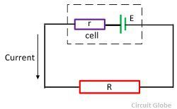
Non-Ideal Batteries and EMF
Real-world batteries exhibit internal resistance that affects circuit performance. This leads to the concept of electromotive force (EMF, ): Where:
: EMF
: Terminal voltage
: Current
: Internal resistance
Key Points:
EMF is the energy per unit charge supplied by a power source.
Internal resistance reduces the effective voltage available to the circuit.

Conclusion
Resistivity and resistance are vital concepts in understanding how materials and circuits behave under electric current. From Ohm’s law to resistor configurations and EMF, mastering these principles enables the design and analysis of efficient electrical systems. Whether troubleshooting a circuit or designing a new device, these tools provide the foundation for innovation and problem-solving.


