5.1 Torque and Rotational Statics
Torque & Rotational Statics
Torque is the rotational analog of force. It is the force that causes an object to rotate around its axis or pivot point. Understanding torque and its relationship with rotational statics is essential for analyzing systems involving levers, gears, and other rotational mechanics. The unit for torque is Newton-meters (N⋅m).
What is Torque?
Torque (τ) is the rotational effect of a force applied at a distance from the pivot point. It is defined mathematically as:
τ = r × F = rFsinθ
Where:
τ: Torque (N⋅m)
r: The distance (radius) from the axis of rotation to the point of force application (m)
F: The applied force (N)
θ: The angle between the force vector and the lever arm (degrees or radians)
The direction of torque follows the right-hand rule, indicating whether the torque induces clockwise or counterclockwise rotation.
Example of Torque in Action
Imagine opening a door. The farther from the hinges you push, the easier it is to open. This is because torque increases with the length of the lever arm. The equation explains why applying force perpendicular to the door results in maximum torque (since sin90° = 1).
Conditions for Rotational Equilibrium
In static systems, achieving equilibrium requires that two conditions are met:
First Condition of Equilibrium: ∑F = 0
This means the net force acting on the object is zero, ensuring no linear acceleration.
Second Condition of Equilibrium: ∑τ = 0
This means the net torque acting on the object is zero, ensuring no rotational acceleration.
Together, these conditions ensure the system is in both translational and rotational equilibrium.
Key Concepts in Torque and Rotational Statics
Direction of Torque:
Clockwise torques are typically considered negative.
Counterclockwise torques are positive.
Lever Arm:
The perpendicular distance between the axis of rotation and the line of action of the force is crucial for determining torque. A longer lever arm produces a greater torque for the same force.
Balancing Torques:
In equilibrium, the clockwise and counterclockwise torques must balance out. For example: ∑τclockwise = ∑τcounterclockwise
Moment of Inertia
Moment of inertia (I), also known as rotational inertia, measures an object’s resistance to rotational acceleration. It depends on the object’s mass distribution relative to the axis of rotation. The general formula for moment of inertia is:
I = ∑mr²
Where:
m: Mass of each particle (kg)
r: Distance of the particle from the axis of rotation (m)
Common Moments of Inertia
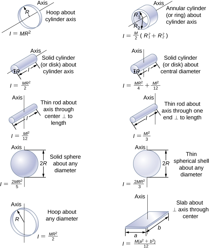
Rod (axis at the center): I = (1/12)ML²
Rod (axis at one end): I = (1/3)ML²
Solid disk: I = (1/2)MR²
Hollow cylinder: I = MR²
Solid sphere: I = (2/5)MR²
Hollow sphere: I = (2/3)MR²
These formulas are essential for solving problems involving rotational dynamics.
Parallel Axis Theorem
The parallel axis theorem allows us to calculate the moment of inertia when the axis of rotation is shifted from the center of mass. It is expressed as:
I = Icm + Mh²
Where:
I: Moment of inertia about the new axis
Icm: Moment of inertia about the center of mass
M: Mass of the object (kg)
h: Distance between the center of mass and the new axis (m)
Application
If you’re designing a rotating machine or analyzing the stability of structures, the parallel axis theorem simplifies calculations when the axis of rotation isn’t at the center of mass.
Practice Problems
Problem 1: Balancing Torques
Two children push on opposite sides of a door during play. Both push horizontally and perpendicular to the door. One child applies a force of 17.5 N at a distance of 0.6 m from the hinges. The second child pushes at a distance of 0.45 m. What force must the second child apply to keep the door from rotating?
Solution: Using ∑τ = 0 for equilibrium:
17.5 N × 0.6 m = F2 × 0.45 m
F2 = (17.5 N × 0.6 m) / 0.45 m F2 = 23.33 N
Problem 2: Moment of Inertia
Calculate the moment of inertia of a solid disk (mass = 2 kg, radius = 0.5 m) rotating about its center.
Solution: Using the formula for a solid disk:
I = (1/2)MR² I = (1/2)(2 kg)(0.5 m)² I = 0.25 kg⋅m²
Problem 3: Parallel Axis Theorem
A uniform rod of mass 4 kg and length 2 m has a rotational inertia of (1/12)ML² about its center. Find its moment of inertia if the axis is shifted to one end.
Solution: Using the parallel axis theorem:
I = Icm + Mh² Icm = (1/12)ML² = (1/12)(4 kg)(2 m)² = 1.33 kg⋅m² h = L/2 = 1 m
I = 1.33 kg⋅m² + (4 kg)(1 m)² I = 1.33 kg⋅m² + 4 kg⋅m² I = 5.33 kg⋅m²
Real-World Applications
Engineering: Torque calculations are crucial in designing engines, turbines, and bridges to ensure structural stability and efficiency.
Sports: Understanding torque helps improve performance in sports like baseball (pitching), gymnastics (spins), and cycling (pedaling).
Astronomy: Torque and rotational statics explain the stability and rotation of celestial bodies like planets and stars.
Conclusion
Torque and rotational statics form the foundation of understanding rotational motion. By mastering concepts such as torque, moment of inertia, and equilibrium conditions, you can analyze and predict the behavior of rotating systems, from simple levers to complex machinery. This knowledge has vast applications in engineering, physics, and everyday life, making it a vital topic in the study of mechanics.
Torque and Rotational Statics FAQs
1. What is torque in physics?
Torque is the rotational equivalent of force, describing the tendency of a force to cause an object to rotate around an axis. It is calculated as: where:
: Torque,
: Distance from the axis of rotation (lever arm),
: Applied force,
: Angle between the force and lever arm.
2. What are the units of torque?
The SI unit of torque is the newton-meter (N•m).
3. What is rotational statics?
Rotational statics studies objects in rotational equilibrium, where the sum of all torques acting on the object is zero, resulting in no angular acceleration.
4. What is the principle of rotational equilibrium?
For rotational equilibrium, the net torque acting on an object must be zero:
5. How does torque depend on the lever arm?
Torque increases with the length of the lever arm. A longer lever arm requires less force to produce the same torque.
6. What is the moment arm in torque?
The moment arm is the perpendicular distance from the axis of rotation to the line of action of the force.
7. How does torque affect rotational motion?
Torque causes changes in angular velocity, leading to rotational acceleration. It is analogous to force in linear motion.
8. How is torque used in everyday life?
Examples include:
Turning a wrench.
Opening a door.
Using a seesaw.
9. What is the relationship between torque and angular acceleration?
The rotational equivalent of Newton’s second law is: where:
: Moment of inertia,
: Angular acceleration.
10. What is the center of gravity?
The center of gravity is the point where the weight of an object effectively acts. It influences torque and stability in rotational systems.
11. What are clockwise and counterclockwise torques?
Clockwise torque: Rotates an object in the clockwise direction.
Counterclockwise torque: Rotates an object in the counterclockwise direction. For equilibrium, the sum of clockwise and counterclockwise torques must balance.
12. How do forces at different angles affect torque?
The effectiveness of a force in producing torque depends on its angle. Maximum torque occurs when the force is perpendicular to the lever arm ().
13. How is torque calculated for multiple forces?
Net torque is the sum of individual torques:
14. What is a couple in rotational statics?
A couple consists of two equal and opposite forces acting at different points, producing pure rotational motion without translation.
15. How does torque relate to stability?
An object is stable if the line of action of its weight passes through its base of support. Torque due to weight outside the base causes toppling.
16. What is the role of friction in rotational statics?
Friction provides resistance to motion, generating torques that can prevent slipping or rotation.
17. What is the rotational analog of work?
Rotational work is given by: where is the angular displacement.
18. How is rotational power defined?
Rotational power is the rate of doing rotational work: where is angular velocity.
19. What is the moment of inertia in torque?
Moment of inertia quantifies an object’s resistance to rotational acceleration and depends on the mass distribution relative to the axis of rotation.
20. How does the distribution of mass affect torque?
Mass distributed further from the axis increases the moment of inertia, requiring greater torque to achieve the same angular acceleration.
21. What is rotational equilibrium in engineering?
In engineering, rotational equilibrium ensures structures or machines do not experience unwanted rotation, maintaining stability and functionality.
22. How is torque applied in mechanical systems?
Torque is crucial in gears, pulleys, and engines to transmit rotational motion and power efficiently.
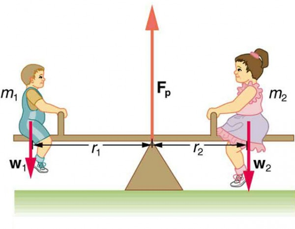
23. How does a seesaw demonstrate rotational statics?
A seesaw is in equilibrium when the clockwise and counterclockwise torques due to weights on either side balance.
24. What is the significance of torque in cranes?
In cranes, torque determines the load-carrying capacity and stability. Longer booms require counterweights to balance torque.
25. How does torque relate to gears?
In gears, torque is transferred between gears, with larger gears producing higher torque at lower rotational speeds.
26. What are real-life examples of torque?
Tightening bolts with a wrench.
Using a crowbar to lift objects.
Balancing on a bicycle.
27. How does torque affect door hinges?
Applying force farther from the hinge increases torque, making it easier to open or close doors.
28. How is torque measured?
Torque is measured using tools like torque wrenches, which provide precise control over applied torque.
29. What is a torque vector?
Torque is a vector quantity, with direction determined by the right-hand rule: curl your fingers along the rotation direction, and your thumb points along the torque vector.
30. How does the angle of force application influence torque?
Torque is maximized when the force is perpendicular to the lever arm (). Smaller angles reduce the effective torque.
31. What is the equilibrium condition for a rotating object?
For rotational equilibrium:
Net torque is zero ().
Angular acceleration is zero.
32. How is torque used in flywheels?
Flywheels store rotational energy, and torque is applied to increase or decrease their angular velocity, balancing energy fluctuations.
33. How do counterweights affect rotational systems?
Counterweights balance torque, preventing rotation or toppling in systems like elevators and cranes.
34. What is static equilibrium?
Static equilibrium occurs when an object is at rest, with both net force and net torque equal to zero.
35. How does torque apply to levers?
Levers amplify force by increasing the length of the lever arm, allowing smaller forces to generate significant torque.
36. How is torque used in propulsion systems?
In propulsion systems, torque determines the rotational speed and thrust generated by engines or propellers.
37. What is the role of torque in rotating wheels?
Torque applied to wheels causes rotation, converting engine power into motion in vehicles and machinery.
38. How does torque affect rolling motion?
Torque generates angular acceleration, enabling rolling objects to move while maintaining contact with the surface.
39. What is the significance of torque in sports?
Torque influences performance in sports like baseball (bat swing), gymnastics (rotations), and cycling (pedaling force).
40. How does torque relate to energy conservation?
In rotational systems, torque determines energy transfer, balancing work done by and against rotational forces.
41. What is the torque in a balanced beam?
In a balanced beam, the sum of torques from weights on either side of the pivot is zero, maintaining equilibrium.
42. How does torque apply to wind turbines?
In wind turbines, torque from wind-generated forces rotates the blades, converting kinetic energy into electrical power.
43. How does torque prevent tipping in vehicles?
Torque generated by the vehicle’s center of gravity must remain within the base of support to prevent tipping during turns.
44. What are the safety considerations for torque in machinery?
Over-torque can damage components or cause accidents. Torque limits and control systems ensure safe operation.
45. How does torque affect gyroscopic stability?
Torque applied to spinning gyroscopes causes precession, stabilizing their orientation and resisting external forces.
46. How is torque balanced in bridges?
In bridges, torque from loads is counteracted by support forces and structural design to maintain equilibrium.
47. What is the role of torque in robotics?
Torque in robotic joints determines the force and precision of movements, crucial for tasks like lifting or rotating.
48. How does torque relate to angular momentum?
Torque changes angular momentum over time, influencing the rotational motion of systems:
49. How does torque influence bicycle stability?
Applying torque to handlebars adjusts a bicycle’s direction and balance, maintaining control during motion.
50. Why is understanding torque and rotational statics important?
Understanding torque and rotational statics is essential for designing stable systems, improving mechanical efficiency, and solving real-world engineering problems.
