3.3 Steady State Circuits
Steady-State Circuits: Comprehensive Guide
Steady-state circuits form the backbone of electrical engineering and physics. They are characterized by a consistent flow of electrical current, with no changes over time. This guide explores key concepts, principles, and practical applications of steady-state circuits to help deepen your understanding and improve problem-solving skills.
What is a Circuit?
A circuit is a closed loop that allows electrical current to flow. If the loop is broken, such as by a switch or a faulty component, electricity will not flow, and the devices in that circuit will cease to function. Examples of disruptions include:
Switches: Interrupt the flow intentionally.
Blown Bulbs: Break the loop due to component failure.
To function correctly, a circuit must be complete, allowing electrons to return to their starting position.
Types of Circuits: Series and Parallel
Series Circuits
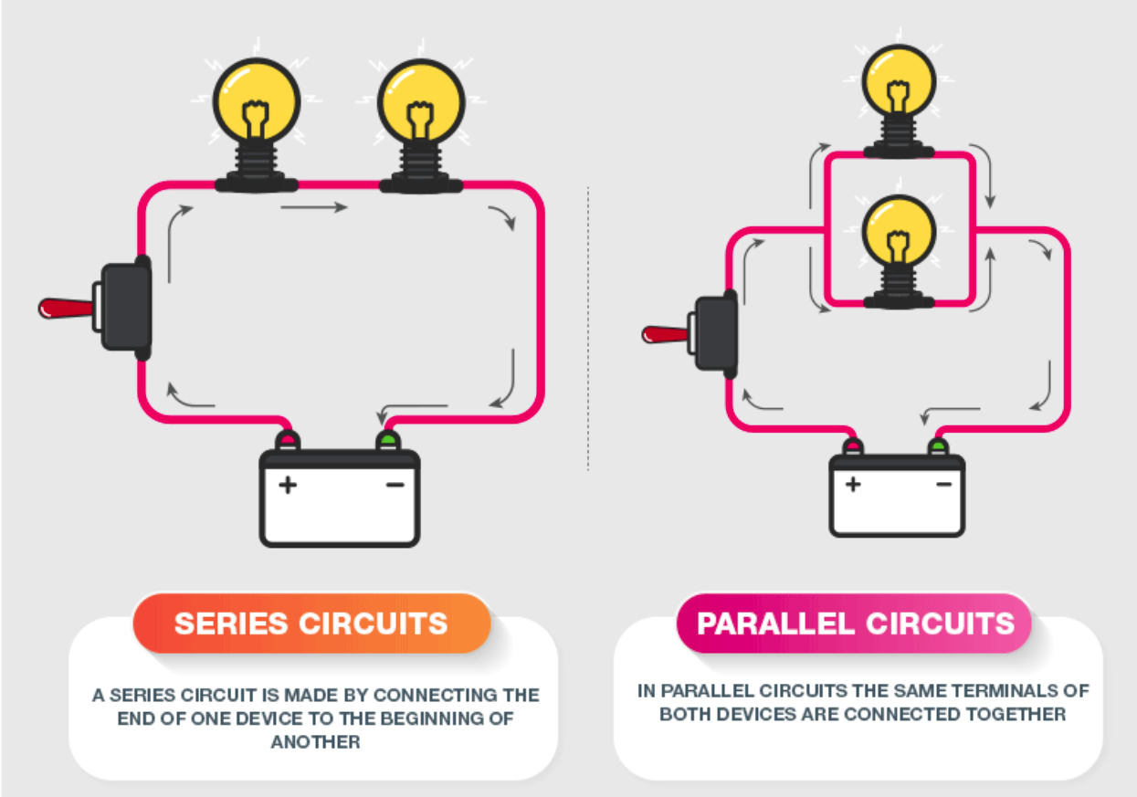
In a series circuit, all components are connected in a single pathway. The current flows through each component sequentially. Characteristics include:
Single Path: All current must flow through each component.
Total Resistance: The sum of individual resistances:
Parallel Circuits
In a parallel circuit, components are connected across multiple pathways. Current divides and flows through each pathway independently. Characteristics include:
Multiple Paths: Current splits among pathways.
Total Resistance: Calculated using the reciprocal formula:
Kirchhoff’s Laws
Kirchhoff’s Voltage Law (KVL)
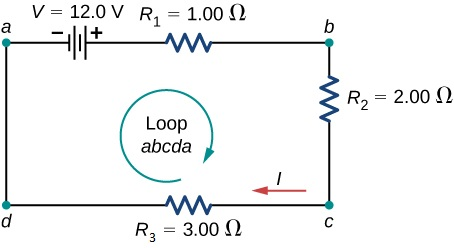
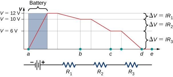
KVL states that the total voltage in a closed loop equals the sum of the voltage drops across all components. Mathematically:
This principle ensures energy conservation within the loop, as all electrical energy provided by the voltage source is transferred to the components.
Kirchhoff’s Current Law (KCL)
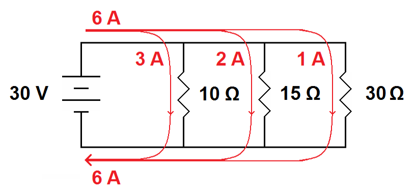
KCL asserts that the total current entering a junction equals the total current leaving it. Mathematically:
This rule follows the principle of charge conservation, ensuring no charge is lost or created at a junction.
Resistors in Circuits
Resistors in Series
In a series configuration, resistances add up directly:
Resistors in Parallel
In a parallel configuration, the reciprocal of the total resistance is the sum of the reciprocals of individual resistances:
Adding more resistors in parallel reduces the total resistance, akin to opening additional lanes in a traffic system.
Resistivity and Current Density
Resistivity is a material’s property that quantifies how much it resists the flow of electric current. It is influenced by:
Material Type: Conductors have low resistivity, while insulators have high resistivity.
Temperature: Higher temperatures generally increase resistivity.
The relationship between electric field and current density is given by:
Where is the resistivity of the material.
Non-Ideal Batteries and EMF
In real-world applications, batteries have internal resistance, which must be accounted for in circuit calculations. The total energy supplied by the battery is represented by the electromotive force (EMF, ), and the relationship between terminal voltage and EMF is:
Where:
: Terminal voltage
: Electromotive force
: Current
: Internal resistance

Circuit Symbols and Measuring Tools
Circuit Symbols
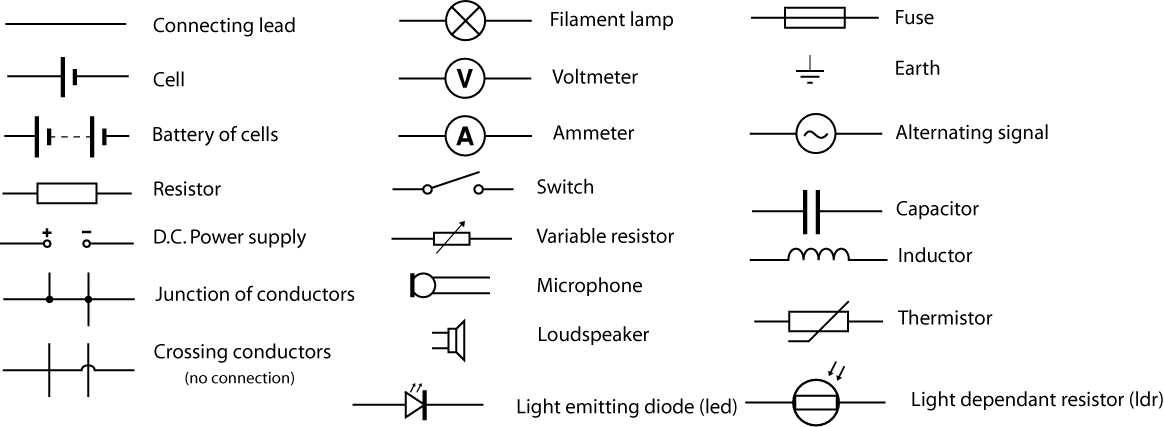
Electrical diagrams use standardized symbols to represent components, such as:
Battery: Voltage source.
Resistor: Opposes current.
Switch: Opens or closes the circuit.
Measuring Tools
Voltmeter: Measures potential difference; connected in parallel with high internal resistance.
Ammeter: Measures current; connected in series with low internal resistance.
Example Problems
Problem 1: Equivalent Resistance
Question: What is the equivalent resistance of the circuit below?
Solution:
Parallel Combination:
Series Combination:
Problem 2: Internal Resistance
Question: What is the internal resistance of the battery in the circuit below?
Solution:
Calculate Total Resistance:
Find Internal Resistance: Using series and parallel rules, determine based on the circuit configuration.
Steady-state circuits are essential for understanding electrical systems. By mastering series and parallel configurations, Kirchhoff’s laws, and concepts like resistivity and EMF, you can analyze and design efficient circuits for various applications.


